
In a previous article titled "Understanding BMW's Valvetronic System", we discussed the workings of a mechanical system BMW had developed to alter the lift of the intake valves on equipped engines in some detail. While Valvetronic systems are reasonably robust and reliable, they are not immune to faults and effects that affect their operation, and in this article, we will discuss some of these issues, as well as provide some diagnostic and servicing tips. Let us start with-
The first iteration of the Valvetronic system* was introduced in 2002 on the N62 (V8), and N73 (V12) engines. The redesigned N52 inline six-cylinder engine, which was introduced during 2006, received the second-generation Valvetronic system, while the third, and current iteration of Valvetronic systems is in use on almost all BMW engines across the range of BMW vehicles.
*See the article “Understanding BMW’s Valvetronic System” for more details.
Regardless of the age of the Valvetronic system on any given BMW model, all iterations of the system are said by BMW to produce an effect known as “throttle-free” load control. Some BMW literature also refers to this as an “engine control mode” that is distinct and separate from a control mode in which the throttle opening controls the engine load. While this distinction can be confusing, the best thing to do is to remember that when a BMW engine runs at idle, the throttle opening is held to an opening of between 3% and 4% by the DME, while the amount of commanded intake valve lift controls the volume of air that enters the cylinders.
During idling, the DME can adjust the intake valve lift (without increasing the throttle opening) to maintain and improve both idling speed and quality. Although the range of valve lift adjustment during idling is very small, the fact that some adjustment is possible during idling clearly illustrates the concept of engine control through valve lift, as opposed to controlling the engine through making changes to the throttle opening. Whether or not this constitutes true engine control is debatable, but that is somewhat beside the point.
The point is that under some operating conditions, the amount of valve lift does indeed control the amount of air entering the cylinders, which has major implications for-
We have all used intake manifold vacuum readings as diagnostic aids, but things are a little different on Valvetronic-equipped BME engines. For instance, the low rate of airflow during idling causes a low intake manifold vacuum, and although a BMW engine can run at idle when the pressure in the intake manifold is equal to atmospheric pressure, the crankcase ventilation and EVAP systems require a vacuum to function.
Therefore, the DME is programmed to maintain the intake manifold vacuum at around 50 millibar, which is equal to about 1.5 inches of Mercury when the engine is idling. This vacuum is determined by the percentage of throttle opening, which as we have stated elsewhere, is maintained at between 3% and 4% during idling. Bear in mind though that when you are diagnosing rough or uneven idling issues, the degree of throttle opening is almost imperceptible, so resist the temptation to condemn the throttle body as the cause of the rough idling problem.
Nonetheless, the best place to start diagnosing idling issues is at the differential pressure sensor on the intake manifold. This sensor registers the actual vacuum inside the intake manifold, as opposed to the absolute manifold pressure, as on almost all other vehicle makes. As an additional check, bear in mind that under KOEO (KEY ON ENGINE OFF) conditions, a high-end scan tool should display an intake manifold vacuum value of between 0 and 1 millibar, as opposed to between about 980 and 1000 millibar, which indicates atmospheric pressure.
However, if the engine has forced induction, the manifold pressure/vacuum sensor acts as a MAP sensor; therefore, you should see a manifold pressure of around 1000 millibar (or slightly less) under KOEO conditions.
This distinction is important from a diagnostic perspective because the differences in the manifold vacuum readings between naturally aspirated engines and forced induction engines running at idle will tell you what type of manifold pressure sensor you are dealing with. This will, in turn, tell you if the engine is running in throttle control mode, or valve lift control mode.
Knowing the difference between control modes is also important for reasons that involve the VANOS (variable valve timing) system. For instance, almost all VANOS faults will cause the engine to a) revert to full throttle control mode, and b), to advance the eccentric shaft to the almost maximum valve lift position. This condition will typically produce manifold vacuum values of between about 600 and 690 millibars on all Valvetronic-equipped engines.
Thus, if the idle quality is poor but a scan tool displays an eccentric shaft position of less than 30 degrees* of rotation while the manifold vacuum is at about 50 millibars, the engine is running in valve lift control mode. Therefore, the poor idling problem is unlikely to involve the Valvetronic system.
*Full rotation = 225 degrees.
We hope that the above section has given you a better understanding of how to use manifold vacuum readings when diagnosing Valvetronic issues, which brings us to-

Image source: https://www.searchautoparts.com/sites/www.searchautoparts.com/files/images/Photo-4-copy.jpg
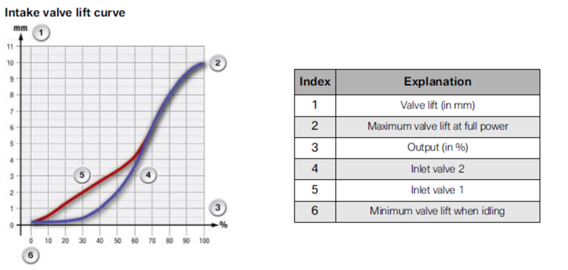
The above graph shows the valve lift curves of two intake valves on one cylinder of a fully functional Valvetronic-equipped engine. In this example, the red curve describes the valve lift curve on the non-adjustable valve, while the blue curve describes the lift curve for the adjustable valve.
The purpose of making only one intake valve per cylinder adjustable is to improve combustion as the result of increased turbulence in the intake charge. If the system works as designed, it produces measurable reductions in both fuel consumption and exhaust emissions, while improving engine power at low to intermediate engine speeds, at the same time.
Nonetheless, while there are slight differences in the valve lift curves for different engines, this example is representative of what the intake valve phasing of a Valvetronic-equipped engine should look like. Here is what the numbers mean, but note that the vertical axis (1) represents intake valve lift in millimetres, while the horizontal axis (3) represents power output as a function of engine speed-
2) Maximum valve lift on both valves at maximum engine power output; in this condition, the eccentric shaft is at its maximum position to allow the full cam profile to act on the adjustable valve. As a result, the lift of the adjustable valve matches that of the non-adjustable valve.
4) Note that the point labelled “6” indicates the point at which the adjustable valves’ lift is limited to about 0.2mm until the engine reaches about 25% of its rated output. After this point, the valve lift increases rapidly, albeit not linearly to engine speed. As a practical matter, the rate at which valve lift is increased is determined by input data from the throttle position sensor, throttle pedal position sensor, and the intake manifold vacuum/pressure sensor, among others.
5) Note the sharp rise in the red curve (non-adjustable valve) at between 50% and 60% of rated power output. Note also that since the non-adjustable valve is not affected by the operation of the Valvetronic system, the sharp rise is a function of the VANOS system. As such, the sharp rise (in the red curve) is a function of changes in the non-adjustable valve's timing, as opposed to its lift and duration.
Why is any of this important? It is important because when the Valvetronic and VANOS systems work together as designed, the results are, a), an idle quality that is unmatched by almost any other vehicle make or engine, and b), a smooth, seamless increase in engine power throughout the engine’s operating range.
Note though that this was often not the case on engines that were equipped with first-generation Valvetronic systems, since the points of contact between the eccentric shaft and intermediate arms consisted of contact pads, as opposed to the rollers that feature in second-, and third-generation Valvetronic systems. In poorly maintained engines these contact pads wore out or wore out unevenly, which resulted in the intake valves opening by unequal amounts. Among other things, this caused poor idling, hard starting, and in some cases, severe misfires at low to intermediate engine speeds and/or loads.
It is perhaps interesting to note that it was possible to increase the minimum valve lift on first-generation Valvetronic systems from 0.3mm, to 0.8mm with a scan tool. The purpose of this test was to eliminate or mitigate the effects of uneven mechanical wear of some Valvetronic components. Therefore, if the idle quality improved when the valve lift increased, the problem typically related to excessive or uneven mechanical wear of some components. If, however, the idling quality did not improve or change when the valve lift increased, the problem usually involved issues in the ignition and/or fuel delivery systems.
Fortunately, the introduction of rollers to replace contact pads in second-, and third-generation Valvetronic systems have all but eliminated excessive or uneven mechanical wear of Valvetronic components as a cause of rough idling issues. However, since the DME needs to know the position of the eccentric shaft at all times when the engine is running, poor idling, hard starting, excessive fuel consumption, misfires, and other driveability issues are usually caused by-

Image source: https://www.searchautoparts.com/sites/www.searchautoparts.com/files/images/Photo-5-copy.jpg
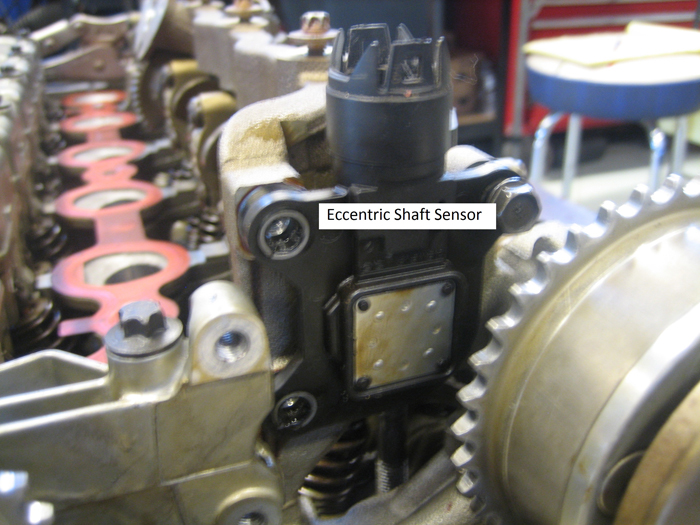
Since the DME has to “know” the exact position of the eccentric shaft at all times to exert precise control over the intake valve lift, the system uses a complex position sensing system that consists of two separate sensors that are incorporated into a single assembly.
Such a sensor is shown in the image above, and while it is usually possible to scope the operation of “normal” position sensors, this is not possible with Valvetronic position sensors. These sensors are of a complicated design that operates on a “magneto-resistive” principle that does not lend itself to scoping even with advanced laboratory-grade oscilloscopes. Nonetheless, one sensor in the assembly monitors the position of a segmented magnetic ring inserted into the end of the eccentric shaft, as shown below-

Image source: https://www.searchautoparts.com/sites/www.searchautoparts.com/files/images/Photo-5-copy.jpg
One sensor is known as the measuring sensor because it measures the actual position of the eccentric shaft relative to a known reference point, while the other sensor is known as the "evaluation" sensor, which is used as a double check on the plausibility or accuracy of the eccentric shaft's position as reported by the measuring sensor.
In practice, the measuring sensor is monitored continuously by the DME, while data from the evaluation sensor is typically only checked and compared to data from the measuring sensor during valve lift adjustments. However, the data from both sensors is not linear, meaning that input data from neither sensor correlates directly to the amount of rotation of the eccentric shaft. The only thing that can be checked with a scan tool is the actual position of the eccentric shaft in degrees of rotation from 0 degrees at minimum valve lift position, to about 225 degrees at maximum valve lift position.
Therefore, if a scan tool with bi-directional controls can rotate the eccentric shaft throughout its possible range of rotation, and fault codes are present that relate to eccentric shaft range and/or performance issues, the best course of action to take is to replace the eccentric shaft position sensor. In fact, position sensor failures are arguably the most common cause of Valvetronic issues on first- and second-generation Valvetronic systems, and replacing the position sensor is usually the quickest remedy.
NOTE: Third-generation Valvetronic systems use position sensors that are integrated into the eccentric shaft actuator motors, and can therefore not be replaced on their own.
Knowing that Valvetronic position sensors cannot be scoped removes a lot of guesswork from diagnosing these systems, but there is one more possible cause of rough running and/or poor idling quality we need to discuss, this possible cause being-
Although the loss of compression is seldom caused by Valvetronic issues, the loss of compression on one or more cylinders occurs more often than you might have thought. However, since valve lift and valve timing are controlled by the Valvetronic and VANOS systems respectively, it can happen that a compression test by whatever method yields incorrect or misleading results.
To eliminate this, BMW has incorporated a compression testing procedure into its ITSA factory (or equivalent) scan tools. This procedure requires you to rotate the (disconnected) eccentric shaft drive motor manually using an Allen key until the eccentric reaches a position of exactly 176 degrees of rotation, at which position a compression test will yield accurate results.
For instance, acceptable compression values for the N52 engine fall in a range of between 1 387 kPa, to about 1 447 kPa, but this value can increase significantly if the eccentric shaft is set to less than 176 degrees because the intake valves close sooner. Similarly, compression values will decrease if the eccentric shaft is set to more than 176 degrees because the intake valves close later, which leaves us with this-
Although this article is not intended to be the last word spoken on Valvetronic diagnostics, it should nevertheless enable any reasonably competent technician to diagnose and repair most of the common issues that afflict Valvetronic systems.
Unlike similar systems that control and/or alter the operation of intake valves on other vehicle makes/brands, Valvetronic systems are relatively simple systems that rarely suffer mechanical failures- except for position sensor failures as the result oil ingress into their connectors. Thus, a measure of common sense, the ability to think critically, and at least a working knowledge of how Valvetronic systems work is often all you need to recognise and repair a range of issues on these systems.
