
If you are not a BMW specialist or have not had much exposure to BMW valve train issues, you might have wondered why some post-2001/2002 BMW engines suffer from issues such as rough idling, excessive fuel consumption, lack of power, and at times, hard starting. In many cases, the listed symptoms are the result of defects in the Valvetronic system, so in this article, we will take a closer look at the inner workings of Valvetronic technology, as well as some of the Valvetronic related trouble codes you can expect to encounter. Let us start with this question-
In its simplest form, the Valvetronic system controls valve lift by mechanical means, and in conjunction with BMW’s VANOS variable valve timing system, intake valve lift, intake valve duration, and intake valve timing are infinitely adjustable. The advantages of this system include reduced fuel consumption, reduce exhaust emissions, reduced engine pumping losses, and improved power delivery over a significantly broader range of engine speeds/loads than is possible to achieve with VANOS alone. However, while Valvetronic systems do deliver quantifiable improvements in engine performance, and especially at low and intermediate engine speeds, these systems are not trouble-free, so let us look at-

Image source: https://www.searchautoparts.com/sites/www.searchautoparts.com/files/images/Photo-3-copy.jpg
This image shows a somewhat simplified schematic representation of the principal components of a Valvetronic equipped valve train but before we get to specifics, it is perhaps worth noting that there is no advantage to fully opening the intake valves on a BMW engine at low to intermediate speeds and loads.
In fact, while the intake valves on most engines typically open by anything between 9mm and about 11mm, BMW engineers managed to achieve just over 80% of the power mapping during the development of the first generation of Valvetronic technology on almost all BMW engines with an intake valve lift of just 3mm, or even less in some cases. Put in another way, this means that Valvetronic-equipped BMW engines can produce their maximum rated power output over the lower 80% of their operating ranges with an intake valve lift of 3mm (or less) and that full valve lift is only required during wide-open throttle conditions to produce maximum power.
Having said that, let us look at what the arrows on the above schematic represent, which is important if we are to understand how this system works in practice-
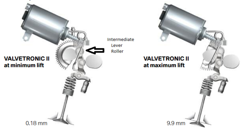
The image below shows the actual layout of some of the principal components of a second-generation Valvetronic system-

Image source: https://www.searchautoparts.com/sites/www.searchautoparts.com/files/images/Photo-2-copy.jpg
In this image, the two RED arrows indicate the direction of movement of the intermediate arm’s foot, these movements being the mechanism that reduces or increases the lift and duration of the intake valve. Nonetheless, here is how the system works in practice-
In Valvetronic systems, the intake camshaft(s) is/are not in direct contact with the rocker arms. Instead, the camshaft acts on an intermediate arm that is in direct contact with an eccentric shaft that (depending on its position) can allow only a part of the cam profile to act on the intermediate arm. The position of the eccentric shaft is controlled and managed by the DME (BMW-speak for the ECU) with a brushless motor and a set of drive gears, while the position of the eccentric shaft, in degrees or rotation relative to an end stop, is monitored by a dedicated position sensor.
In practice, the DME can rotate the eccentric shaft (via the drive gears) through about 225 degrees of rotation to move the intermediate arm towards or away from the camshaft. In its minimum position, the eccentric shaft moves the intermediate arm so far away from the camshaft that only a very small section of the cam profile acts on the intermediate arm. In this position, the intake valve lift on second and third-generation* Valvetronic systems is only about 0.18mm.
*Note that on first-generation Valvetronic systems, a) minimum intake valve lift was about 0.3mm, and b), that the contact point between the camshaft and intermediate arm was a contact pad, as opposed to the rollers that feature in later iterations of the system. However, this design was prone to excessive, rapid, and uneven mechanical wear of the contact point if oil changes were neglected or skipped, hence the move to more wear-resistant rollers.
In the maximum position, the eccentric shaft moves the intermediate arm closer to the camshaft, to allow the entire cam profile to act on the rocker arms via the intermediate arm. During normal engine operation, the eccentric shaft can be at almost any position between its minimum and maximum positions, depending on the engine speed and load. It is important to note, however, that the introduction of smaller and more powerful brushless actuator motors (that now fit inside the valve covers) in second, and third-generation Valvetronic systems makes it possible to change the intake valve lift from maximum to minimum and, vice versa, in less than 300 milliseconds, which makes changes in intake valve lift undetectable by average drivers.
In terms of practicalities, reducing the intake valve lift by large amounts has the effect of accelerating the flow of charge air into the cylinders, which improves mixing of the fuel and air, which as we know, improves combustion. Moreover, since reducing valve lift also changes the valve timing, the intake valves can be opened and closed later or sooner, depending on operating conditions. Perhaps most importantly though, limiting valve lift also has the effect of reducing, if not eliminating, the oscillating pressure waves in intake manifold runners that can impede the flow of air through the runners, which brings us to the point often made in some discussions about Valvetronic systems, this point being-

Much of the confusion around how BMW's Valvetronic systems work stems from the statement by BMW that the flow of intake air, and hence, the engine load are controlled by the small amount of intake valve lift, as opposed to being controlled by the throttle opening. BMW calls this approach “throttle-free [engine] load control”.
Worse, though, some commentators claim that Valvetronic systems obviate the need for a throttle body at low to intermediate engine speeds/loads. Alternatively, some discussions claim that the Valvetronic system performs the function of the throttle body at low to intermediate engine speeds/ loads, and/or that a Valvetronic-equipped BMW engine only needs a throttle body to control intake airflow under WOT conditions.
Do these statements make any sense to you? While it is not for this writer to tell BMW’s design engineers that they are wrong, these statements do not make any sort of sense to this writer, so let us think about it for a bit. For instance, diagnosing Valvetronic issues can be made a whole lot easier if one remembers that without a throttle body, the DME has no way of controlling the idle speed and quality, which it does by opening the throttle plate to between about 3% and 4%.
Therefore, regardless of the limited intake valve lift that causes relatively a high manifold vacuum pressure (low vacuum), a BMW engine cannot run at idling speed without a throttle body. This means that saying intake air airflow is a function of valve lift during minimum valve lift conditions, as opposed to being a function of the throttle opening, is complicating matters unnecessarily.
As a practical matter, when a BMW engine is running at idling speed, the DME collects data about the airflow entering the engine as reported by the MAF sensor, but bear in mind that the MAF sensor can only measure the airflow after it has passed through the throttle body. Given this fact, it is difficult to see how Valvetronic technology obviates the need for a throttle body at low engine speeds since a throttle plate is required to regulate idling speed.
We hope we have cleared up some of the confusion about throttle bodies on Valvetronic-equipped engines, so let us move on to the question of-
The good news is that given the relative mechanical simplicity of the Valvetronic system, it is fairly robust in the sense that it rarely, if ever, fails catastrophically. However, the bad news is that issues with the movement or rotation of the eccentric shaft are common, and is arguably the most common problem on Valvetronic systems.
In most cases, the repair is difficult, time-consuming, and expensive, but whatever the cause of a binding or sticking eccentric shaft though, the typical symptoms of a binding or sticking eccentric shaft could include one or more of the following-
NOTE: While electrical problems such as abnormal resistances and/or voltages/currents can affect the operation of Valvetronic systems, failures of actuator motors are relatively rare, as are programming issues that cannot be resolved with software patches or updates. In practice, the most common electrical problem on Valvetronic systems is failures of or defects in eccentric shaft position sensors.
This last point is especially important to keep in mind since the DME will adjust the intake valve lift to about a mid-range opening when the engine is switched off to allow for more air and fuel to enter the cylinders during cold starts. Thus, a defective or malfunctioning eccentric shaft position sensor could cause the DME to fail to set an appropriate valve lift distance at shut down, which will almost always cause cold start issues.
Nonetheless, the real problem with diagnosing Valvetronic issues involves fault codes and the lack of technical information on what the various trouble codes mean. For instance, if you are using a BMW-compliant scan tool, you might find one or more BMW- specific fault code like 2A59, 2A5F, and 2A63, among several others. While these codes relate specifically to Valvetronic issues, the problem is that they will almost certainly not be accompanied by definitions to point you in the right diagnostic direction, which makes having the codes next to worthless since it is difficult to obtain relevant trouble code definitions and service/repair information even from official BMW sources, which begs the question of-
Given the difficulty of obtaining reliable technical/repair/service information on Valvetronic systems, many independent mechanics guess at possible causes and solutions when working on these systems, which often lead to misdiagnoses, mistakes, and unhappy customers. However, to help you diagnose Valvetronic issues, this writer searched through his own workshop’s archives for information, and happened across this list of BMW-specific trouble codes and their definitions-
|
Trouble Code |
Definition |
Trouble Code |
Definition |
|
2A59 |
Valvetronic Eccentric Shaft Sensor 1 |
2A69 |
Valvetronic Voltage Supply Servomotor 1 |
|
2A5B |
Valvetronic Eccentric Shaft Sensor 1 |
2A6B |
Valvetronic Power Limitation Servomotor |
|
2A5D |
Valvetronic Eccentric Shaft Sensor 1 |
2A6C |
Valvetronic Adaptation |
|
2A5F |
Valvetronic Eccentric Shaft Sensor 1 |
2A6D |
Valvetronic Electrical Overload Protection 1 |
|
2A61 |
Valvetronic Adaptation 1 |
2A6F |
Valvetronic Minimum Lift Exceeded |
|
2A63 |
Valvetronic Servomotor 1 |
2A70 |
Valvetronic Servomotor |
|
2A67 |
Valvetronic Internal Fault |
2A71 |
Valvetronic Relief Relay |
While the definitions given here are accurate since they are from an official BMW source, they don't tell you much, if anything in terms of what to look for, diagnostically speaking. Nonetheless, this writer has found helpful diagnostic advice and/or information on several occasions by asking questions on technical sites and even on BMW user forums, which is often the quickest way to find the information you want or need.
However, if you are using a high-end generic tool instead of a BMW-specific scan tool, you might extract fault codes that are in the more familiar PXXXX format. There are proper definitions, and even some technical information available for these codes, and below are some details of relevant BMW-specific Valvetronic trouble codes as well as some diagnostic pointers; also from this writer's own archives-
P1014 - Valvetronic Eccentric Shaft Sensor Reference
This code almost invariably indicates a defective or malfunctioning eccentric shaft sensor that records a position value that is at variance with the position value the DME is expecting to see.
P1017 - Valvetronic Eccentric Shaft Sensor Plausibility
This code usually indicates an eccentric shaft position that falls outside of the accepted or possible range of values.
P1017 - Valvetronic Eccentric Shaft Sensor Plausibility
Although this code is similar to P1014, P1017 usually relates to wiring issues in the Valvetronic system that could include damaged, burnt, shorted, disconnected, and corroded wiring, and/or connectors. Other possibilities are poor electrical connections, abnormal electrical resistances, or mechanical damage to the eccentric shaft.
P1023 - Valvetronic Adjustment Range
Although this code is similar to P1017, P1023 usually indicates mechanical damage to the eccentric shaft that impedes or hinders the eccentric shaft's free movement.
P1030 - Valvetronic Monitoring Sluggish Movement
This code is similar to Range or Performance issues in actuators or sensors in other systems, in the sense that it indicates a slow or sluggish movement of the eccentric shaft during valve lift adjustments. Typical causes could include poor electrical connections, a damaged or defective actuator motor, low system voltages, or a binding/sticking eccentric shaft.
P10DF - Valvetronic Overload Protection Output Stage System Shutdown
The presence of this code will typically cause the Valvetronic system to be deactivated, and in some cases, a limp mode to be initiated. Typical causes include a binding or sticking eccentric shaft that might cause an electrical overload or short circuits in the system. Note though that these conditions will not necessarily cause fuses to blow because the DME will typically deactivate the Valvetronic system before an electrical overload can reach crisis proportions.
P10E0 - Valvetronic Overload Protection Control Motor System Shutdown
This code typically indicates malfunctions, defects, or short circuits within a Valvetronic actuator motor itself.
P10E1 - Valvetronic System No Travel Detected
This code typically relates to a failure of the eccentric shaft position sensor to report the movement of the shaft in any direction. Note this code is more likely to indicate a failure of the position sensor than to indicate a failure of the eccentric shaft to rotate.
P10E7 - Valvetronic Overload Protection Output Stage Overload
This code usually indicates issues in the system that detects electrical overloads in the Valvetronic system. Note though that we do not recommend attempting repairs of this code without access to a large-scale wiring diagram, and technical information that lists exact resistance values for all circuits in the Valvetronic system. Guesswork or mistakes made when diagnosing this code could result in extensive damage to one or more control modules, including the DME.
P10E8 - Valvetronic Control Motor Overload
Although this code is similar toP10E0,P10E8 will typically set before an electrical overload in the Valvetronic system can become so severe that the DME deactivates the system as a safety precaution. Typical causes include a slightly sticking or binding of the eccentric shaft, or electrical resistances that while abnormal, still fall below a certain critical maximum threshold. In other words, if the fault gets worse, the Valvetronic system could be deactivated by the DME.
So now that we know a little more about Valvetronic related fault codes and their definitions, where does one begin to look for the actual problem when fault codes are present? While there are many possible starting points, long experience has taught that scoping the eccentric shaft’s range of movement often produces the most usable data in the shortest possible time. Note that this procedure requires that you activate the eccentric shaft with the bi-directional controls on a high-end scan tool, so if you have a suitable tool the example known-good scope trace below is what you should see-

Image source: https://www.searchautoparts.com/sites/www.searchautoparts.com/files/images/Photo-7-copy.jpg
In this example, the scan tool is performing a Valvetronic limit relearn procedure, which, incidentally, is a required procedure after completing any repairs or service on any part of a Valvetronic system.
Nevertheless, doing this procedure will tell you a lot about the overall health of the Valvetronic system, For instance, in this example, the two traces (red and blue) on the bottom represent voltage patterns obtained from the two connections on an actuator motor. The green trace in this example was captured from one of the motor wires, and it shows the current the motor was drawing during the test.
The most important aspect of this capture is the two current values that are labelled 35 Amps, and 44 Amps, respectively. These values apply to all Valvetronic systems, regardless of the engine, and they represent the points when the eccentric shaft reaches and learns the position of each end stop. During this test, the rotation through 225 degrees between end stops takes about 1.5 seconds.
So in practice, a binding or sticking eccentric shaft might produce voltage and/or current patterns that differ significantly from this known-good example. Moreover, if the rotation takes longer than 1.5 seconds to complete, it could be that something is impeding the free movement of the eccentric shaft, without it actually sticking. Note though that in cases where the test runs for longer than 1.5 seconds, you will almost certainly see either elevated current values or erratic voltage patterns that could include signal drop-outs and /or spikes, which leaves us with this-
While we hope that this article had provided you with some new insights into the workings of BMW’s Valvetronic system, we must also include a cautionary note against underestimating the need to adhere to prescribed service procedures when working on these systems.
In most cases, you need to perform service and/or repairs in a prescribed series of steps to avoid damage to the system, or personal injury (or both) so in a follow-up article, we will discuss some of the finer points of servicing Valvetronic systems.
